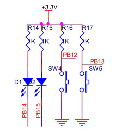
We need to generate PWM signal on PB14(embeded with an LED D1, or D2 if you like)
> when the `PB14` output `LOW`, `D1` will light up.
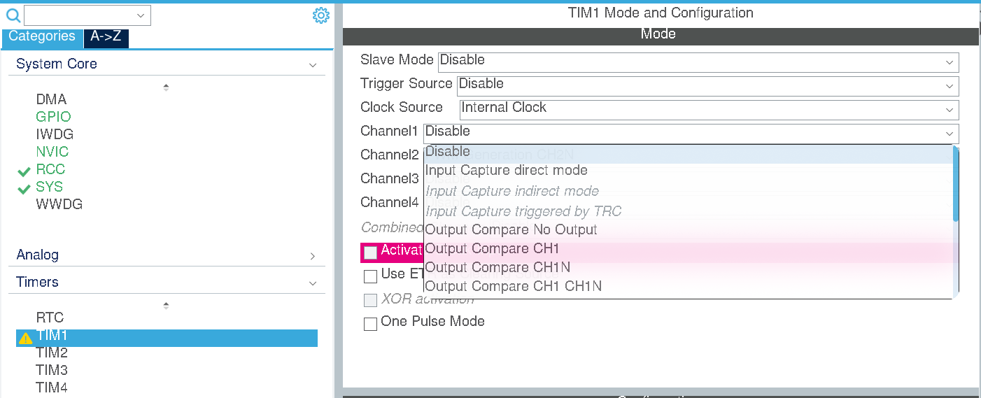
In STM32, Input Capture and Output Compare is configured in Timer channels.
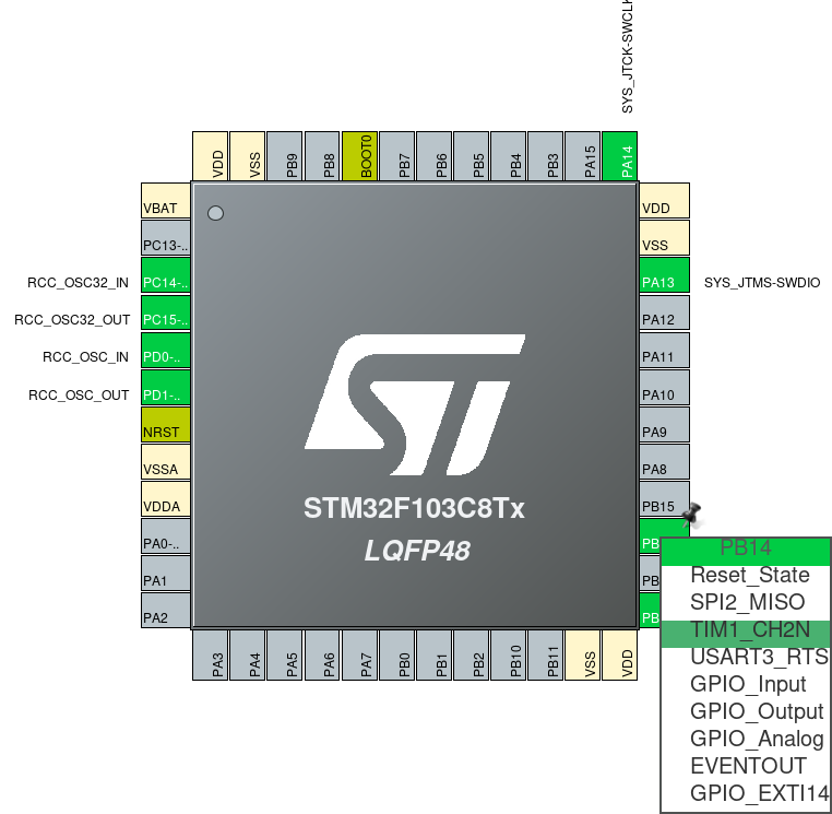
Let’s check which Timer is connected to PB14
It's the `CH2N` channel of timer 1.
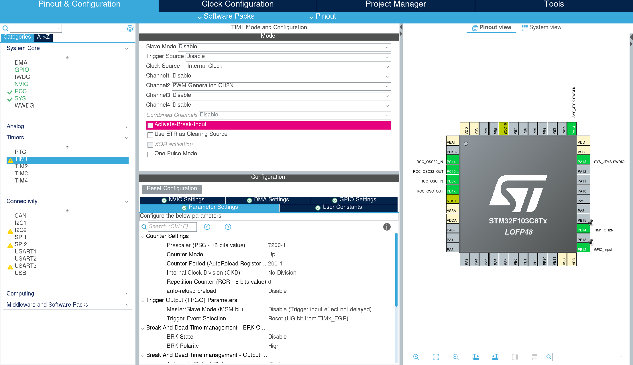
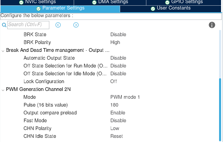
Then we configure timer 1.
Prescaler: 7200-1
Counter Period: 200-1 (50Hz)
Pulse: 180 (duty cycle of 90%; TIM_CNT 0~179: HIGH, TIM_CNT 180~199: LOW)
CHN Polarity: LOW (needed for CHN)
> CHxN is the complementary channel of CHx in Timer1.
> If the polarity of CHxN and CHx are different, the two channels will follow the same output pattern, otherwise they will be complementary
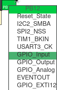
Also remember to configure PB12 (SW4) as GPIO_Input.
> You can try to use Input Capture to capture the press action of the button (as indicated in lab manual, i.e. connecting `PB12` to `PA0`).
## Code
Init PWM in `main()`:
1
2
3
4
/* USER CODE BEGIN 2 */
HAL_TIM_PWM_Start(&htim1, TIM_CHANNEL_2);
HAL_TIMEx_PWMN_Start(&htim1, TIM_CHANNEL_2);
/* USER CODE END 2 */
Get the press/release action of the button (PB12):
1 2 3 4 5 6 7 8 9 10 11 12 13 14 15
int pressed = 0; /* USER CODE BEGIN WHILE */ while (1) { // main loop /* USER CODE END WHILE */ /* USER CODE BEGIN 3 */ if (!HAL_GPIO_ReadPin(GPIOB, GPIO_PIN_12) && pressed == 0) { pressed = 1; // what to do when pressed } elseif (HAL_GPIO_ReadPin(GPIOB, GPIO_PIN_12) && pressed == 1) { pressed = 0; // what to do when releassed } } /* USER CODE END 3 */